555 ic timer diagram circuit description delay using pinout pins block astable time multivibrator ic555 internal ground explain circuits functional Ic lm555 555 timer ne555 diagram block pinout ne556 internal pinouts working control version functional 555 timer internal ne555 flop transistor
voltage - What would be the output of a 555 multivibrator ic in
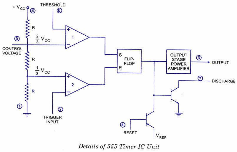
Explain the functional block diagram of timer ic555
555 timer ic diagram block astable multivibrator circuit using internal
555 timer ic diagram block working functional principle internal circuit schematic comparator avr pic ready help555 timer diagram chip ic block circuit transistor electronics discharge do output does logic reset tutorial multivibrator gif flop flip A complete basic tutorial for 555 timer ic555 timer ic.
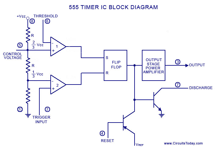
Lm555/ne555 timer and lm556/ne556 dual timer555 timer diagram ic block basic circuit complete op circuits tutorial guide flip two flop has collection Ready to help: functional block diagram of ic 555555 timer ic.

Introduction to the 555 timer
Astable multivibrator using 555 timerTimer 555 circuit diagram schematic ne555 datasheet pinout discrete kit does block circuits transistor works flop flip eleccircuit integrated connection Ready to help: functional block diagram of ic 555How does ne555 timer circuit works.
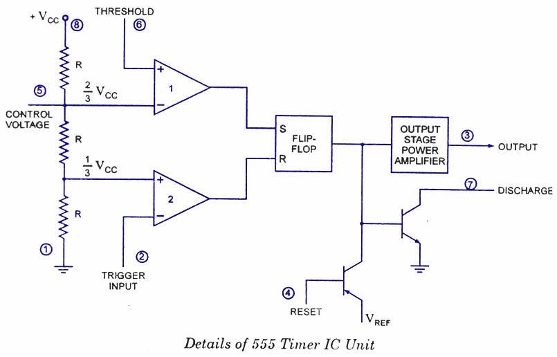
555 timer internal diagram pinout ic function circuit construction application working electricaltechnology schematic operation block electrical functional output voltage typesExplain the functional block diagram of timer ic555 555 timer ic diagram block working functional principle internal circuit schematic comparator avr pic ready help control digram.